Member-only story
Towards Industry 4.0 — #7 RNG, Random Number Generator in Siemens S7–1200
The Digital Transformation Journey to Industry 4.0 starts by understanding Industry 3.0
Andi Sama — CIO, Sinergi Wahana Gemilang with Cahyati S. Sangaji
In Summary
- Implement a Random Number Generator using Siemens' LGF (Library of Generic Functions).
- PLC Hardware: Siemens S7-1200 DC/DC/DC.
- Software tools: Siemens TIA Portal on Windows 11.
- Programming `Language: Ladder Logic Diagram.
- This article's supporting files (Siemens S7-1200) are available on Github - https://github.com/andisama/RNG-with-Siemens-PLC-S7-1200
Although it seems trivial in any higher-level programming language such as C++, Java, or Python, the random number generator is not commonly supported in default installation software for Programmable Logic Controllers (PLC). E.g., no available function block for generating random numbers that we can instantly use in the ladder logic diagram.
This article illustrates using the random number generator in Siemens PLC S7–1200 through Siemens TIA Portal (Total Integrated Automation). The function is part of Siemens’ generic functions (LGF) library.
How Does It Work?
When the Start Button is pressed, the program starts. The Blue_Light at digital output address %Q0.0 is energized with a frequency: 2Hz (energized and not energized two times in a second).

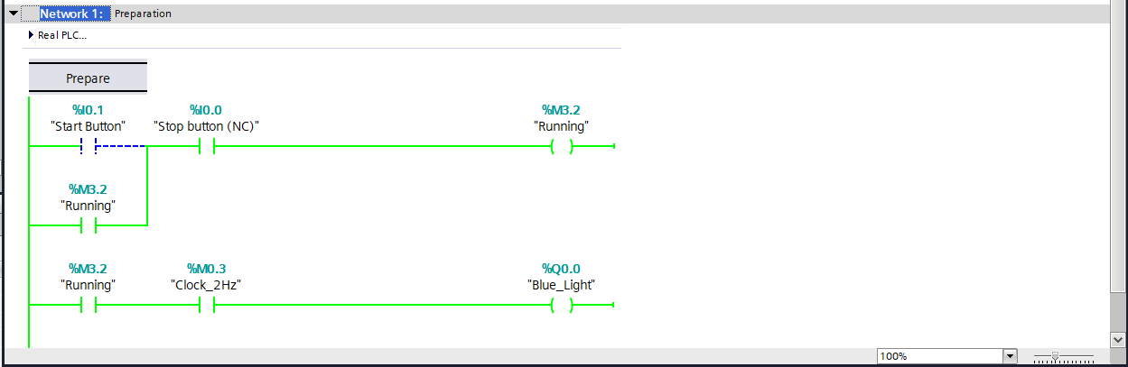
When the “Running tag” at memory address %M3.2 is set, “network 2” within the main organization block (OB1) runs.

Result — PLC’s Digital Outputs with Lamps
When the four digital outputs, %Q0.4, %Q0.5, %Q0.6, and %Q0.7, are connected to 24VDC lamps, the result when the program runs is as follows (video).