Towards Industry 4.0 — #4 PLC Programming, A Traffic Light Controller Use Case with SFC + SCADA
The Digital Transformation Journey to Industry 4.0 starts by understanding Industry 3.0
Andi Sama — CIO, Sinergi Wahana Gemilang with Cahyati S. Sangaji
In Summary

- Implementation of one of PLC's programming languages: SFC. Using Open PLC Editor and Open PLC Runtime.
- Applied to a use case for One-Way Traffic Light Controller with Pedestrian override.
- Completed with visualization using SCADA, using ScadaBR.
- This article's supporting files (open plc source files) are available on Github.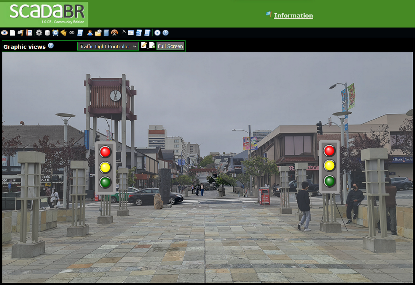
The Industry 4.0 initiative has been driving the need for OT & IT convergence for more than a decade to modernize Operational Technology (OT) by leveraging Information Technology (IT). Industry 4.0 promotes end-to-end digitization of manufacturing and other industrial processes by monitoring and acting on real-time data as they occur.
In the journey towards Industry 4.0, OT can leverage IT such as Cloud Computing, the Internet of Things (IoT), and Artificial Intelligence (AI). Blockchain technology will play an important role when moving to Industry 5.0 later.
Understanding existing technologies in Industry 3.0 (at the Operational Technologies level or OT) would be the foundation for transforming into Industry 4.0.
Industrial Automation
There are two types of industrial automation: discrete and analog. We can identify the difference in the finished products and whether they can be easily quantified.
Manufacturing cars, bottled water, and shoes are discrete automation as the finished product can easily be quantified. In contrast, generating household gas, manufacturing cakes or ice cream, and producing oil are analog automation examples, as the finished products are not easily quantified.
Operational Technologies
In most Industry applications (including factories), OT infrastructure has been designed for 24x7 operation and generates a lot of data. The design is for the components to be operational for a long lifespan, like 20, 40, or 50 years.
It is common for factory operations, for example, to run continuously for weeks, months, or even years. Similarly, it reminds us of the 24x7 Information Technology (IT) operation in Banks or Telecommunication Providers.
OT includes software and hardware devices (controllers, sensors, and actuators). Some hardware devices are configurable. OT includes software such as Enterprise Resource Planning (ERP), primarily for accounting purposes. Advanced OT has additional software like Manufacturing Execution System (MES) and Customer Relationship Management (CRM).
Please see more discussion on Operational Technology in (Andi Sama, Cahyati S. Sangaji) “Towards Industry 4.0 — #1 IT/OT Convergence, A Digital Transformation Journey.”
For this article, let’s focus on the Programmable Logic Controller (PLC) and the implementation of the traffic light controller use-case.
PLC
A production line in a factory consists of several different machines. One PLC controls multiple field devices of one or several machines. It may also control and monitor machines across several production lines. From PLC to field devices, there are complex and various interfaces. Another challenge is properly integrating different PLC brands to acquire aggregated production data.
PLC Programming Languages
In PLC, there are variations of programming languages to do automation. The five common programming languages are Ladder Logic Diagram (LAD), Function Block Diagram (FBD), Sequential Function Chart (SFC), Instruction List (IL), and Structured Text (ST).
This article implements a use case for traffic light control with SFC. Note that the ladder logic diagram is the most popular programming language.
There are three sections for the implementation:
- Implementing a One-Way Traffic Light Controller with Open PLC Editor.
- Deploying the SFC program in Open PLC Runtime.
- Visualization using ScadaBR.
Please see more discussion on PLC and Implementation with Ladder Logic Diagram in (Andi Sama, Cahyati S. Sangaji, 2022a) “Towards Industry 4.0 — #3 PLC Programming, A Mixer Use Case with Ladder Logic Diagram.”
Section 1 — Implementing One-Way Traffic Light Controller with Open PLC Editor
Download Open PLC Editor for Windows here.
Let’s look at a Traffic Light Controller for a one-way street with a pedestrian override button. The traffic light sequence will be as follows.
RED → RED + YELLOW → GREEN → YELLOW
When the light is ON, it will have a predefined ON-time for each color controlled by a Timer. The pedestrian override button is applied to the GREEN color. So, when the GREEN color is active, and the pedestrian push button is activated, the light will change immediately to YELLOW without waiting for the timer to expire.
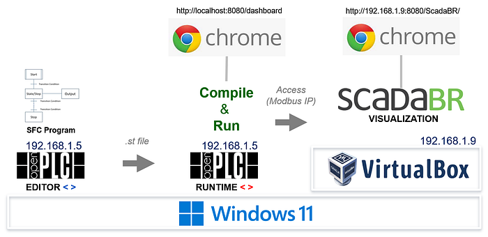
Let’s look at the following illustration of how the SFC program is created in Open PLC Editor, deployed to Open PLC Runtime, and accessed by ScadaBR. All in the same physical machine running Windows Operating System.
Programming the PLC using the Sequential Function Chart
We use Open PLC Editor software on Microsoft Windows (Open Source PLC Software, 2022). Open PLC is an open-source application that complies with IEC 61131–3, in which we can design using Ladder Logic, Structured Text, Instruction List (IL), Function Block Diagram (FBD), or Sequential Function Chart (SFC).
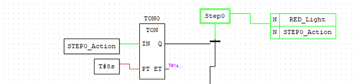
a. Initial Step (Step0)
Let’s start with our first section of the SFC that turns RED_Light when the program has just started.

We implement this using STEP (Step0) with action and transition.
Step0 activates the action to set the RED_Light variable to TRUE and will transition to the next STEP (Step0_1) when the transition connection condition is TRUE.
The Timer function block (TON0) controls the transition from Step0 to Step0_1. In this case, the transition from Step0 to Step0_1 occurs if 8 seconds have passed since the start (the T#8s parameter).
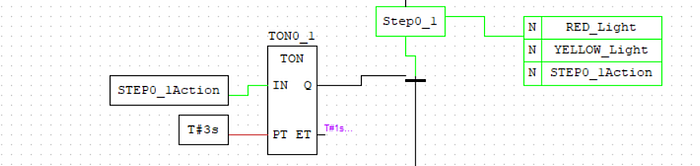
b. Second Step (Step0_1)
Likewise, Step0_1 activates the action to set the RED_Light and YELLOW_Light variables to TRUE and will transition to the next STEP (Step1) when the transition connection condition is TRUE.
The Timer function block (TON0_1) controls the transition from Step0_1 to Step1. In this case, the transition from Step0_1 to Step1 occurs if 3 seconds have passed.
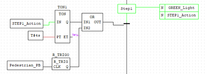
c. Third Step (Step1)
The third step is no different than the first two steps, except that the delay can be bypassed if the pedestrian push button is activated.
Step1 activates the action to set the GREEN_Light variable to TRUE and will transition to the next STEP (Step2) when the transition connection condition is TRUE.
The Timer function block (TON1) controls the transition from Step1 to Step2. In this case, the transition from Steo1 to Step2 occurs if 4 seconds have passed OR the Pedestrian_PB is activated (the signal changes from 0 to 1).
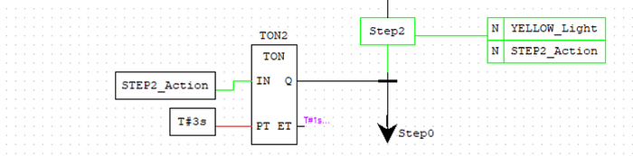
d. Fourth Step (Step2)
Like the first two, Step2 activates action to set the YELLOW_Light variable to TRUE and will transition back to the first STEP (Step0) when the transition connection condition is TRUE.
The Timer function block (TON2) controls the transition from Step2 back to Step0. In this case, the transition from Step2 to Step0 occurs if 3 seconds have passed.
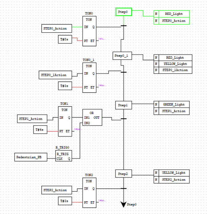
A Completed Sequential Function Chart
The following shows a complete implementation of the SFC for executing the traffic light controller use case.
Section 2 — Deploying the SFC program in Open PLC Runtime
Download Open PLC Runtime for Windows here.
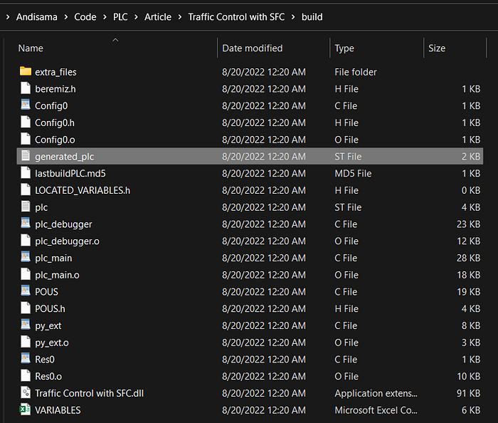
Once the program is compiled successfully in Open PLC Editor, the “generated plc.st” file is created in the ./build directory. This file must be uploaded to the Open PLC Runtime to run independently of Open PLC Editor.
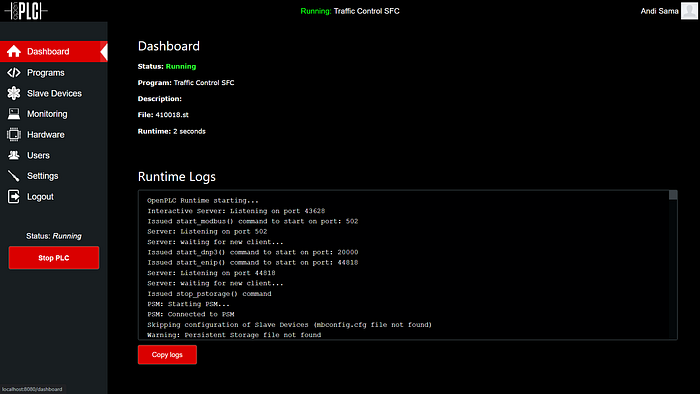
As the program was designed to start automatically, we can monitor the output RED_Light, YELLOW_Light, and GREEN_Light as the program runs. First, the RED_Light turns ON for 8 seconds.

Then, both RED_Light and YELLOW_Light turn ON for 3 seconds.

Next, GREEN_Light turns ON for 4 seconds.
Finally, YELLOW_Light turns ON for 3 seconds. And the program starts all over again from the beginning.
Later, the SCADA application (e.g., ScadaBR) can communicate with the Open PLC Runtime to do visualization.
Section 3 — Visualization using ScadaBR
Download ScadaBR for Windows here.
The ScadaBR image we are installing is hosted on the Virtual Box, running on Windows. The setup should be straightforward. It’s on a “different computer.” Therefore we need to point the ScadaBR to the correct IP address of the Open PLC Runtime.
Special Note: Before setting up the IP address for the Open PLC Runtime, please remember that Virtual Box is hosting our ScadaBR image. As we install on the same computer, we must ensure the network setting is set to the actual network adapter we are using.
The following are the sample data source settings. We access ScadaBR from our local computer web browser, pointing to the IP address of ScadaBR running on the Virtual Box.
Some of the important things:
- Give a name to our data source connection (connection type: Modbus IP), e.g., “Open PLC on Windows,” in this example.
- Set the update period to 500 ms to update it in near real-time.
- Set timeout to 1000 ms.
- Set transport type to TCP with keep-alive.
- Set the Host IP Address to the IP address our Open PLC Runtime runs, e.g., 192.168.1.5 in this example.
We are connected if we can read the data from the Open PLC Runtime.
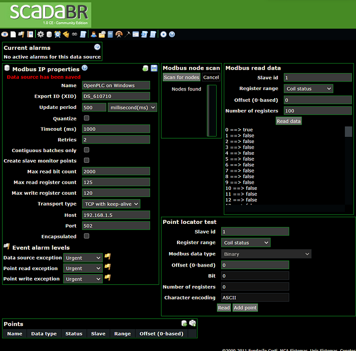

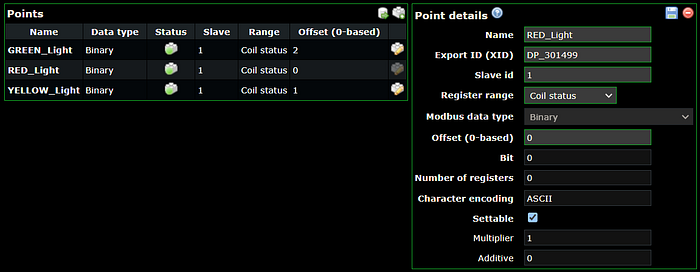
We can add points for our inputs and outputs. e.g., for output (coils status), the Offset (0-based) are 0, 1, and 2, respectively, for RED_Light, YELLOW_Light, and GREEN_Light.
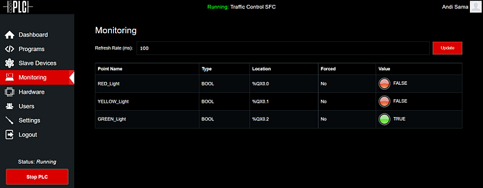
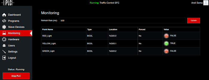
We can then monitor the status of each point in real time.
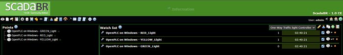
Let’s now visualize this graphically.
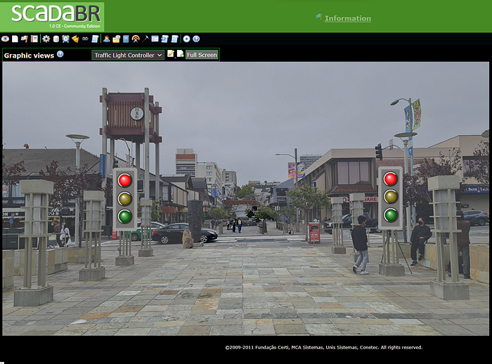
For simplicity, as mentioned before, the program was designed to start automatically. We can monitor the output RED_Light, YELLOW_Light, and GREEN_Light as the ScadaBR gets the real-time statuses from Open PLC Runtime.
Note that the pedestrian override push button is not implemented in this ScadaBR implementation. It can be added easily by adding the input: Pedestrian_PB.
First, the RED_Light turns ON for 8 seconds.
Then, both RED_Light and YELLOW_Light turn ON for 3 seconds.
Next, GREEN_Light turns ON for 4 seconds.
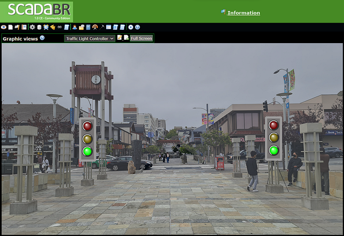
Finally, YELLOW_Light turns ON for 3 seconds. And the program starts all over again from the beginning.

Looking Forward
The (R)evolution, the transformation from Industry 3.0 to Industry 4.0, is happening now. IT and OT teams need to work together, internally or externally.
As in many technological revolutions, people often become the main bottleneck for change as the new technology may affect their jobs and comfort zone. Top Management will play a key role in managing the transformation.
Understanding the driving technologies in Industry 3.0 is important for transforming into Industry 4.0. This article discussed one of the programming languages for PLC, i.e., Sequential Function Chart. Though, there are many areas of technological advancements in Industry 3.0. Some of them are field devices (sensors & actuators), other programming languages for PLC, and robotics, including key applications like Manufacturing Execution Systems (MES) and Enterprise Resource Planning (ERP).
The transition to Industry 4.0 may not be straightforward at once as in one multi-years turn-key project. The iteration approach could be the best to follow. Transforming one area of focus at a time, moving on to the next iteration as business values emerge as previous iteration(s) starts to produce tangible benefits.
References
- 4.0 Solutions, 2022, “No, 80% of Manufacturers have not Started Their Digital Transformation Journey.”
- Andi Sama, Cahyati S. Sangaji, 2022a, “Towards Industry 4.0 — #3 PLC Programming, A Mixer Use Case with Ladder Logic Diagram.”
- Andi Sama, Cahyati S. Sangaji, 2022b, “Towards Industry 4.0 — #2 PLC Programming, ‘Hello World.”
- Andi Sama, Cahyati S. Sangaji, 2022c, “Towards Industry 4.0 — #1 IT/OT Convergence, A Digital Transformation Journey for Automation & Control.”
- Infographics Presentation Template, 2021, Slidesgo and Freepik.
- Open Source PLC Software, 2022, “The first open-source, muti-hardware Programmable Logic Controller Suite.”
- RealPars, 2022, “Online Learning Platform for Automation Engineers.”
- Tech Learning, 2019, “Communication Protocols for Industrial Automation.”
- Walker Reynolds, 2021, “State of Industry 4.0 Keynote Address 2021,” 4.0 Solutions.